The 2018 versions of the Autodesk programs have been out for a while now. You have a point cloud and you need to create a surface from it. Well, if you have the AEC collection, you have two options, 1) Create the surface in Civil 3D or 2) Create the surface in InfraWorks. Which one should you use?

I was working with a client recently that had this very same dilemma so I decided to do a little testing to see how well each option does creating the surfaces. To give a little bit of background on the data set, the point cloud contains around 90 million points and is an agricultural field with a stream running through the middle of it.

Overall_Point_Cloud

Overall Point Cloud in ReCap

This dataset is kind of unique as it has areas that are very flat and fairly consistent as well as areas that vary quite a bit. Creating a single surface in Civil 3D from 90 million points would take a massive amount of time (if it was even possible) so I decided to test this on a smaller scale. I cut out a couple portions of the point cloud, one in the area of the field and one in the area of the stream.

Let’s get to creating the surfaces. I created the surfaces for both areas using both Civil 3D and InfraWorks. In both programs, I maxed out the settings to get the best possible surfaces.

Creating The Surface in InfraWorks

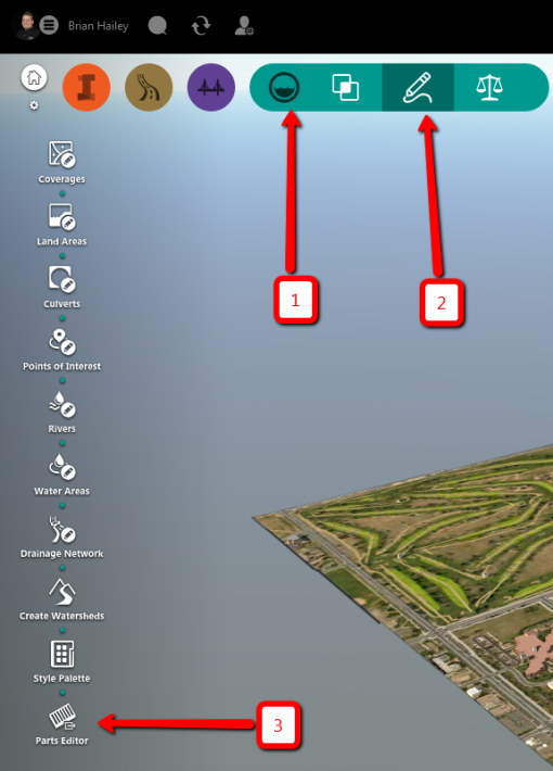
How is this done in InfraWorks? First, I created a new model and imported the ReCap file. Once the point cloud is in the model, I used the command, “Point Cloud Terrain”. This can be found on the “Build, manage, and analyze your infrastructure model” section (Big Orange “I”), and then the “Create and manage your model” (Q-bert looking button).

Terrain_Command_InfraWorks

Point Cloud Terrain Command

The settings I used for generating the terrain can be seen in the following image. I basically set them to give me the best possible terrain I could get from the data. Once I created the surface, I then imported the surface into Civil 3D.

InfraWorks_Point_Cloud_Terrain_Settings

InfraWorks Point Cloud Terrain Settings

Creating the Surface in Civil 3D

To create a surface in Civil 3D 2018, just like with InfraWorks, you must first import the point cloud. On the Insert tab of the ribbon, you can simply attach the ReCap file. Once the point cloud is in the drawing, select it and, on the contextual ribbon tab, choose the command, “Create Surface from Point Cloud”.

Create_Surface_Command_Location

Command to Create Surface from Point Cloud in Civil 3D

Just like with InfraWorks, I created these surfaces so they would max out the data that was available. In the command, I did not change the settings for the number of points being used or the area to use (I had already cropped out smaller areas from the overall point cloud in ReCap). The only settings I changed that would affect the data was on the  Non-Ground Point Filtering section, where I changed it to use the Kriging interpolation filter method.

Kriging_Interpolation

Filter Method set to Kriging Interpolation

How do they compare?

To compare them, I brought the two surfaces for each area into a drawing and then created a volume surface between them. This allowed me to see what the elevation differences were between the two surfaces. I then did an elevation analysis on the volume surface so I can see where these differences are.

The Field

The first one I did was for the area of the field.

Plain_Comparison

Comparison of Surfaces in the Field

If you look at the numbers, you can see that over 96% of the surfaces are within 0.1′ of each other and over 99.8% are within 0.2′. This is really good! If I zoom in on the area of the contours (they are 1′ contours by the way, you can see a little bit more detail.
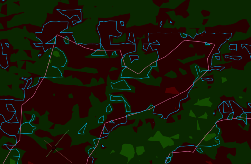
Plain_Contours

Field Contours

The blue contours are from the surface created in Civil 3D whereas the red contours are from the surface created in InfraWorks. One final comparison, lets look at the data density of the two surfaces. How many points are in each of these surfaces?

  • Civil 3D Surface – 356,420 points
  • InfraWorks Surface – 9,993 points

To be fair, I could have decreased the number of points as I was creating the Civil 3D surface but, I maxed out the settings in InfraWorks.

The Stream

I repeated the process for the area around the stream.

Stream_Comparison

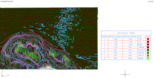
Comparison of Surfaces at the Stream

As you can see, the numbers aren’t quite as good here. In fact, there are areas that are off by up to 8′. I did a similar comparison based on these numbers and found that almost 97% of the surface was within 2′ and almost 99% was within 4′. This isn’t a fair comparison so I reran the analysis using basically the same numbers as for the field (0.1′ increments) but I lumped everything beyond 0.4′ into the same category. This is what I found:

Stream_Comparison_-_2

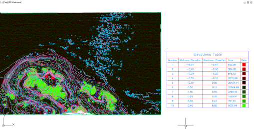
Surface Comparison with 0.1′ Increments

Once again, I ran the numbers and found that 83% was within 0.1′ and 89% was within 0.2′. A little concerning was the fact that over 6.7% was more than 0.4′ off.

Let’s go ahead and zoom in on the contours (again, the blue contours are the Civil 3D surface and the red contours are the InfraWorks surface). I displayed it with and without the volume surface because it was difficult to see all the contours at times.
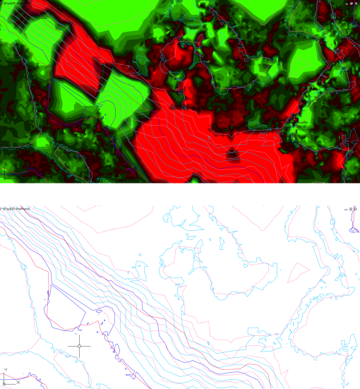
Stream_Contours

Stream Contours

The comparison in size between the two surfaces are:

  • Civil 3D Surface: 773,732 points
  • InfraWorks Surface: 24,474 points

I don’t know how to increase the accuracy of the surface created from InfraWorks any more than it is.

Final Thoughts

Based on the results I’ve received here, which method would I use? Well, if the area is fairly flat and consistent (the field in this example), I would probably go with the InfraWorks surface. If there is a lot of inconsistencies in the data (the stream in this example), I would probably go with the Civil 3D surface.

Remember, you can create an overall surface in InfraWorks, create surfaces in Civil 3D for those areas that it’s needed, and then paste them all together at the end.

What are your thoughts? Have you had much experience with surfaces from point clouds in InfraWorks, Civil 3D, something else all together? Did I get something wrong? Let me know what you think in the comments!

Creating custom parts for your storm sewer or sanitary sewer networks in Civil 3D is not fun. If you’ve ever had to go into Part Builder, you know what I’m talking about; secret variables, odd objects (what’s a COL object anyways?), and sometimes things just don’t work (haven’t been able to create a cut plane in Part Builder in almost a decade). Most of the time when people need to create a new part for a network in Civil 3D, they end up saying, “Whatever is already there, is probably close enough and I’ll just use that instead of doing it right.”

I have good news for you. In the latest version of InfraWorks (InfraWorks 2018.1) there is a new tool called the Project Infrastructure Parts Editor.

Infrastructure Parts Editor.png

Infrastructure Parts Editor in InfraWorks 2018.1

The Infrastructure Parts Editor has been around for quite a while in the Autodesk Labs (it was known as Project Kameleon, yes, with a K) but has recently graduated from labs and is now a full blown program. This tool will allow you to create new parts for use with InfraWorks as well as Civil 3D.

To access the new tool, within InfraWorks click on the drainage tools, then click the pencil drawing a line, and then click on the button for the “Parts Editor”.

Tool in InfraWorks.png

Where to find the Infrastructure Parts Editor in InfraWorks 2018.1

This will then open up an external application called, you guessed it, the Infrastructure Parts Editor.

Application Image.png

Infrastructure Parts Editor

How easy is this? Basically, it’s just pick and choose the parts you want to use. When you create a new catalog (or edit an existing one), you’ll see three options, Assembly, Structure, and Culvert. The parts that will be used in Civil 3D or InfraWorks are the Assemblies. Each assembly is made up of the structures or the culverts.
Assembly_Culvert_Structure.png

When you click on Structure, you’ll see the three different components that make up the structures: Surface Structure, Underground Structure, and Grates or Covers. The Infrastructure Parts Editor has some parts already created that you can start with or you can create your own using Inventor or Inventor LT.

Various_Parts_Sample.png

Sample of Surface Structures

As you can see in the previous image, if none of the predefined shapes work for you, you can create a new shape template and import a .ipt or a .iam file from Inventor.

Additionally, when adding sizes to the different structures, there is an option to export to and import from Microsoft Excel. This should make editing the sizes much easier!

Export_to_Excel.png

Export to Excel

Once all the structures have been created, they will then be combined to make the different assemblies. When creating an assembly (depending on the type of assembly being made), you’ll simply select the three different structure components that you want to combine together. There’s also a section to validate the sizes (don’t want to put a 5′ long grate on a 3′ long inlet).

Assembly_Creation.png

Assembly Creation – Drag and Drop

Once all your assemblies are made, you can then publish the catalog out to either InfraWorks or Civil 3D or both at the same time.

Publish_Catalog.png

Publish Catalog

So, what do you think? Are you going to give this a try? Personally, I’m really excited about this tool and it capabilities for creating custom parts in Civil 3D.


p.s. It also does pressure network parts:
Pressure_Network_Parts.png

AU2016 has come and gone and I’m really excited about point clouds right now. I sat in a lab with Ramesh from Autodesk (using point clouds in InfraWorks) and he gave me the data set he was using as a sample. In the class, he imported the data set into ReCap, trimmed out the unneeded bits, and then brought that into InfraWorks which worked just fine.

Point Cloud Comparison.png

Same Clipped Point Cloud in InfraWorks and Civil 3D

The problem is, if you bring that same clipped point cloud into AutoCAD Civil 3D (or any other AutoCAD based program), the point cloud is not clipped. According to the Autodesk Knowledge Network, this is a known problem and they are working on fixing it however, the only solution currently listed there is, “For InfraWorks the point cloud functionality has been corrected with release 2016”. That’s not much of a solution if you ask me but, I did happen to discover one.

after clipping the point cloud in ReCap, export the project out. This will create a new point cloud that can then be inserted just fine. To export the point cloud, mouse over the House icon, the Down Arrow icon, and then click the Up Arrow icon.

Export.png

Export the Clipped Project

ReCap will then ask you if you want to unify the scans. I’m not exactly sure what this does but I think it combines all the scan files into one file. When I did this, I simply used the default settings and clicked the “space ship” icon.

Unified.png

Huh? A space ship? Really?

Once the project has been exported, simply import that into Civil 3D (or any other AutoCAD based program) and the point cloud will be clipped.

Exported_vs._Original.png

Comparison between original file and exported file in Civil 3D

Hopefully this will help someone out that’s struggling with point clouds in AutoCAD. If you have time, I would love to hear how you are using point clouds in either InfraWorks or Civil 3D. Leave a comment and let us all know!

It’s an exciting time of year for all of us Civil Software Geeks, new software is coming out and we get to see the new and exciting things in the latest release. If you haven’t seen it yet, check out my recap of What’s New in InfraWorks 2016.1. I just downloaded the latest release of Civil 3D 2016 and there are several things that are new. Here are the things in this release and the bold ones are the ones I’ll be discussing:

  • Manage data shortcuts to repair broken shortcuts and replace DWG objects
  • Display vault project objects that exist in subfolders within object type
  • Create data references to objects that exist in different vault projects
  • Import and export IFC (Industry Foundation Class) files
  • Select alignments by layer to be used as width and targets
  • Control the direction of sections in section views
  • Subbassembly Composer loop geometry support
  • Create exclusionary catchments
  • Crossing pipe and pressure pipe profile view labels
  • Pressure pipe labels in section views
  • Import Bridges from InfraWorks into Civil 3D

Just because I’m not discussing them here doesn’t mean they aren’t great improvements, it’s just that I haven’t installed Vault 2016 yet and I haven’t had a chance to learn what an IFC file is yet.

Oh, one more thing before I get started, NO DRAWING FORMAT CHANGE! That’s right, 2016 has the same drawing format as 2013. They’ve broken the 3 year cycle on changing the drawing format.

Manage Data Shortcuts

This one is sweet! Ever have a drawing move or have IT move data to a different drive? I know what you’re thinking, “Brian! They would never do that!” Yeah right. Anyways, this command allows you to repath your data references to a new drawing or to the original drawing if it moved on you. Not only that, you can replace an object in your drawing with a data reference and all the references to that original drawing are maintained!

Manage Data References

Manage Data References

Another fantastic thing that isn’t advertised in the “What’s New”, YOU DON’T HAVE TO SAVE PRIOR TO CREATING DATA SHORTCUTS!!!!!!

Data Shortcuts Without Saving

Data Shortcuts Without Saving

Alignment Targets By Layer

If you have several alignments that a corridor region needs to target, you can now choose the targets by layer.

Alignment Targets By Layer

Alignment Targets By Layer

Section View Display Direction

Section Views have finally caught up to Profile Views, they can be drawing “Right to Left” or “Left to Right”. This should make all those hydraulic modelers happy!

Section View Direction

Section View Direction

Subassembly Composer Loop

Have you needed to put benches in your daylight or a series of walls or something else repetitive in your subassembly? New in 2016, you can now add a loop component that will continue until either a criteria is met or a maximum number of iterations has been done (this keeps it from blowing up on you).

Subassembly Loop

Subassembly Loop

Exclusionary Catchments.

I’ve always liked the idea of creating catchments (or drainage areas or drainage basins or whatever term they use in your area) in Civil 3D from a surface but the problem has always been, but what if I need to subdivide this large basin into smaller ones? For example, I have a road with inlets at a low point and so I create a catchment to that inlet but, the flow in the street is too big. What do you do? You add an inlet upstream and then define a catchment to it. Now in 2016, this new catchment area will be removed from the original catchment so you won’t have duplicate areas!

First Catchment Added

First Catchment Added

Additional Catchment Added

Additional Catchment Added

Crossing Pipe Labels

We’ve been asking for this one for a LONG time and it’s finally here! We can label the a pipe where it crosses in a profile view!

Crossing Pipe Label

Crossing Pipe Label

In the image you can also see the different crossing properties that you can place in your label.

Pressure Pipe Labels in Section Views

In addition to being able to label pressure pipes crossing in a profile view, you can also label them crossing in a section view as well.

Pressure Pipe Crossing Section

Pressure Pipe Crossing Section

Import Bridges from InfraWorks

So, you have InfraWorks 360 with the Roads and Highways and the Bridge tools and you’ve created a nice bridge in InfraWorks. When you import that model into Civil 3D 2016, the bridge comes along as well now!

Bridge from InfraWorks into Civil 3D

Bridge from InfraWorks into Civil 3D

So, what do you think of Civil 3D 2016?

Wouldn’t that be amazing? Set up your InfraWorks model with some zones, put in some signal information at your intersections, place some walking paths, and boom! You have cars and people in your InfraWorks model!

If you find this appealing, you need to head over to Autodesk Labs. There is a technology preview for software that, hopefully, will do just this, AUTODESK LABS: PROJECT COMMUTER – INFRAWORKS.

Currently, the application doesn’t run within InfraWorks but, the powers that be are looking for feedback from you, the valued customer that spends money on software, to determine if this would be worthwhile. Would you like to be able to run travel simulations directly within InfraWorks? I know I would! So get over there and tell them what you think!

HERE is a playlist of examples of what can be down withe the current version of the software (outside of InfraWorks).

<edit 4/3/15>Well, you asked for it so here it is! The March 2015 release of InfraWorks 360 has a preview of traffic simulation in it! Go check it out!

A lot of people I’ve talked to recently have been confused on the new release of InfraWorks 2015. Do I have that tool? If not, why? And where do I get it?

First off, if you haven’t checked out the new InfraWorks, you really should. They’ve made some great changes to it! It’ has a brand new user interface (UI) and some great new functionality.

InfraWorks 2015 User Interface

InfraWorks 2015 User Interface

That’s all nice but, what is available? Well, there are now two versions of InfraWorks for 2015: InfraWorks and InfraWorks 360. If you have one of the suites (Infrastructure Design Suite Premium or Ultimate or the Building Design Suite Ultimate) you have InfraWorks.

InfraWorks

What’s available in InfraWorks? Well, pretty much everything you had in the Premium Suite from last year. This includes:

  • Creating the existing model from GIS data
  • Laying out proposed features (roads, buildings, plants, coverage areas, etc.)
  • Visualization and storytelling
  • Sight analysis
  • Theme features based on their data
  • Shadows and lighting
  • Many more

InfraWorks 360

So, what do you get if you have InfraWorks 360? Well, first off, you get everything you get with InfraWorks plus:

  • Online collaboration with other InfraWorks 360 users.
  • Publishing scenarios for online viewing by anyone.
  • Using Autodesk servers to convert 3D models to InfraWorks data.
  • Model Builder – Create a model simply by choosing the area you are interested in on a map (this is a preview function and may not be in the product in the future).
  • Add-on advanced design tools

Basically, if it touches the cloud, you need InfraWorks 360.

Model Builder Preview

Model Builder Preview

Missing Features?

At first glance, it may seem as though there are some missing features such as the Roadway design, profile optimization, intersections, etc. Well, these are available in that “Add-on advanced design tools” listed above but, they are just that, an add-on. They don’t come with either InfraWorks or InfraWorks 360 but if you want that functionality, they only work on InfraWorks 360, not InfraWorks.

Autodesk Roadway Design

The Autodesk Roadway Design add-on allows you to do the things that were available in the ultimate suite from 2014.  This includes:

  • Design Roadways with true curves and spirals
  • Apply different styles and number of lanes for regions of a road
  • Profiles with vertical curves
  • Intersections between design roads
    • Ability to edit curb returns and add in turn lanes
    • Create site triangles
  • Profile optimization (requires cloud credits)
  • Corridor optimization (requires cloud credits and is currently a preview functionality only)
Design Road Intersection with Site Triangles

Design Road Intersection with Site Triangles

Autodesk Bridge Design

The Autodesk Bridge Design allows you to create very realistic bridges as well as edit things such as number of piers, pier locations, concrete or steel, etc.

Bridge created in InfraWorks 360

Bridge created in InfraWorks 360

Other Add-ons

When InfraWorks 360 first came out for the 2015 version, there was some preview functionality (it timed out May 7th, 2014). Examples of this was Drainage Areas and Culvert Design. The Culvert Design tools did just that, it added a culvert under the roadway. The Drainage Areas would delineate the contributory area to a design point or road that crosses a drainage way. Remember, these are previews of upcoming technology and there is no guarantee that they will be a part of the final product (in other words, don’t buy the software expecting this functionality).
Culvert Design

Licensing

This is the important part! If you have a suite version of InfraWorks, you’re good to go. Nothing new here. But, if you want InfraWorks 360, there are some things you have to be aware of.

Desktop Subscription

InfraWorks 360 and it’s add-ons are only available via Desktop Subscription. What is Desktop Subscription? It’s, in essence, a term license of the software. You purchase a license of InfraWorks 360 and you get access to it for a set term (1 month, quarter, or year). Another thing to note, this license is assigned to a specific user. That user needs an Autodesk ID (they are free) and that license will be assigned to that user. Your software manager can assign those licenses to what ever user in your organization you want.

The nice thing about Desktop Subscription is you can get the software for just the time you need. Got a project that you need 10 users to be able to access the software but the project is only going to last a year, you only pay for that software for a year.

More Information

If you want more information, check out the Autodesk website for comparing the different version of InfraWorks. Since the Autodesk website often changes, I’ve printed out that page and included a link to the .pdf HERE.

If you have any questions about this, make sure you talk to your reseller. If they can’t help you, let me know and one of the sales folks at CAD-1 can help you!

<If you don’t like reading, there’s a video at the bottom of the post.>

I’ve been playing around with InfraWorks for a bit now and I’ve always meant to but never got around to figuring out the Style Rules until now. All I’ve seen with regards to the rules is how to randomize your display. Well, I don’t want to randomize it, I want it to be very specific! I want my offroad roads to look like offroad roads, I want my highways to look like highways, and I want my local roads to look like local roads. Well, read on and see how it’s done! It’s actually a lot easier then I expected.

This is what I’m getting, all the roads look the same:

What I Get

What I Get

And this is what I want, the roads stylized based on their classification:

What I Want

What I Want

First of all, you need a data source with information in it that you’ll use to stylize the InfraWorks objects. In the example I’m using, I downloaded the data from the GIS department for Loveland, Colorado. To get a quick idea of the data that’s in the shape file for the roads, I attached it to a Civil 3D drawing (just drag the .shp file into the Civil 3D drawing) and opened the data table. This particular data source has a field called ROAD_CLASS. Some of the values for ROAD_CLASS are: RAMP, LOCAL, HWY, CLCTR-MINOR, etc.

Road Classification Data Field

Road Classification Data Field

This is the data that I want to use to determine the style of the road. I’ve broken the process up into three steps, adding the data to the model, creating the style rule, and applying the style rule.

Adding the Data to the Model

I’m not going to get into how to add the shapefile to the model here, what I’m going to discuss is how to get that particular piece of data from the shapefile and add it to each road in the model. When configuring the data source (this can be done when it’s added or after the fact if needed), you’ll need to tell InfraWorks to include the piece of data you need. In this example, I’m going to add it to the description of the road. On the Common tab of the Data Source Configuration, simply hit the pull down to add the ROAD_CLASS field to the description of the roads.

Adding GIS Data Fields to InfraWorks Objects

Adding GIS Data Fields to InfraWorks Objects

Note: If you want to add the data to a different property, you can do this on the Table tab of the Data source Configuration dialog box.

Close and refresh and now we are ready to create the Style Rules.

Creating the Style Rule

Now, we want the style of these roads to be determined from the description so, let’s create a Style Rule. To open the Style Rules, select the big orange I in the top left of your model (I’m using 2014 R4 for this), select the button just to the right of it, “Create and manage your model”, and then select Style Rules.

Open the Style Rules Panel

Open the Style Rules Panel

In the Styles Rules, select the tab on the left for the feature you want to add the rules to (in this case I’m going to choose Roads) and then add the new rule by selecting the green plus. Give the rule a name (I’m using the roadway classification here) and then click OK.

Add a Rule

Add a Rule

Once the rule is added, double click on it to edit the rule. In the Rule Editor, you can change the name of the rule and add a description to the rule if you would like. The important part here are the “Expression:” and “Styles:” sections.

Rule Editor

Rule Editor

In the “Expressions:” section, select the Edit button to edit the expression (sounds obvious, doesn’t it?). In the Create Filter Expression dialog box, double click the property you want to filter on (in this case expand out Common and choose Description). This will add that property to the expression. Now, I only want this rule to be applied to the roads with a specific description so, type an equals sign “=” in the expression after DESCRIPTION. Finally, add the property to the expression. If you know it, you can just type it. If you want to select one of the properties that is in the data source, on the right hand side, find the property and then double click on the value to add it to the description.

Create the Expression

Create the Expression

After hitting OK, you’ll be back in the Rule Editor. In the “Styles:” section, simply add the styles you want this rule to apply. If you want them all to be the same, simply add the one style you want. If you want them to vary, you can add multiple styles and then adjust the probability to force one style to be added more often then another.

Completed Rule

Completed Rule

Now continue the process until you’ve added a rule for each roadway type you have.

Rules Created

Rules Created

Applying the Style Rule

This is the easiest part, once the Style Rule has been created, all you need to do is click on the Run Rules button at the bottom of the panel.

Run the Rules

Run the Rules

There are also options to export and import the Rule Styles so you don’t have to recreate them every time you need to do this.

Now get out there and have fun playing around with InfraWorks!

Infraworks. Wow. What a great program. I love this thing, I truly do. If Autodesk keeps up development on this, it’s going to rock the industry. The problem with it as it stands today is, there are four different versions of it. That’s right, four.

Infraworks – Comes with the Infrastructure Design Suite Premium
Autodesk InfraWorks 360 Pro – Available to lease
Autodesk Roadway Design for Infraworks 360 Pro – Available to lease
Infrastructure Design Suite Ultimate – This pretty much tells you what it is.

So, what’s the difference? In short, if you want ALL the tools, you’ll need the Autodesk Roadway Design for Infraworks 360 Pro. It has tools that the Ultimate Design Suite doesn’t have, such as Sight distance analysis and Documentation services. The Documentation services is a cloud service that will allow you to create plan and profile drawings in Civil 3D without needing to open, or even install, Civil 3D (sounds pretty cool to me).

You can find a matrix that shows what each version has HERE. In case the website has changed, I’ve printed a page of the Autodesk website and included it HERE for you to download.