A lot of people I’ve talked to recently have been confused on the new release of InfraWorks 2015. Do I have that tool? If not, why? And where do I get it?
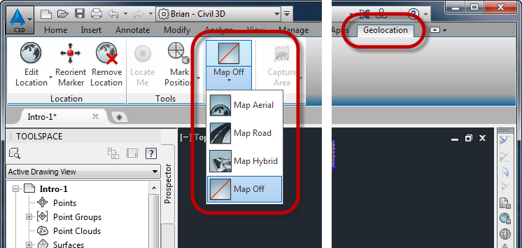
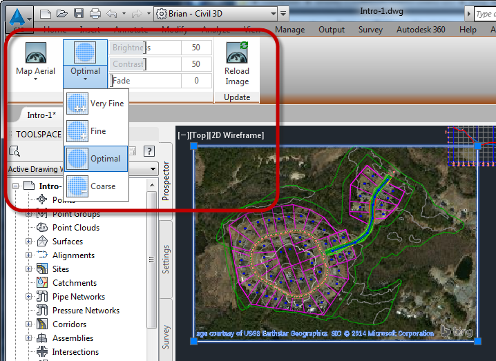
First off, if you haven’t checked out the new InfraWorks, you really should. They’ve made some great changes to it! It’ has a brand new user interface (UI) and some great new functionality.
InfraWorks 2015 User Interface
That’s all nice but, what is available? Well, there are now two versions of InfraWorks for 2015: InfraWorks and InfraWorks 360. If you have one of the suites (Infrastructure Design Suite Premium or Ultimate or the Building Design Suite Ultimate) you have InfraWorks.
InfraWorks
What’s available in InfraWorks? Well, pretty much everything you had in the Premium Suite from last year. This includes:
- Creating the existing model from GIS data
- Laying out proposed features (roads, buildings, plants, coverage areas, etc.)
- Visualization and storytelling
- Sight analysis
- Theme features based on their data
- Shadows and lighting
- Many more
InfraWorks 360
So, what do you get if you have InfraWorks 360? Well, first off, you get everything you get with InfraWorks plus:
- Online collaboration with other InfraWorks 360 users.
- Publishing scenarios for online viewing by anyone.
- Using Autodesk servers to convert 3D models to InfraWorks data.
- Model Builder – Create a model simply by choosing the area you are interested in on a map (this is a preview function and may not be in the product in the future).
- Add-on advanced design tools
Basically, if it touches the cloud, you need InfraWorks 360.
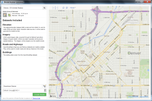
Model Builder Preview
Missing Features?
At first glance, it may seem as though there are some missing features such as the Roadway design, profile optimization, intersections, etc. Well, these are available in that “Add-on advanced design tools” listed above but, they are just that, an add-on. They don’t come with either InfraWorks or InfraWorks 360 but if you want that functionality, they only work on InfraWorks 360, not InfraWorks.
Autodesk Roadway Design
The Autodesk Roadway Design add-on allows you to do the things that were available in the ultimate suite from 2014. This includes:
- Design Roadways with true curves and spirals
- Apply different styles and number of lanes for regions of a road
- Profiles with vertical curves
- Intersections between design roads
- Ability to edit curb returns and add in turn lanes
- Create site triangles
- Profile optimization (requires cloud credits)
- Corridor optimization (requires cloud credits and is currently a preview functionality only)
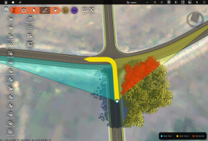
Design Road Intersection with Site Triangles
Autodesk Bridge Design
The Autodesk Bridge Design allows you to create very realistic bridges as well as edit things such as number of piers, pier locations, concrete or steel, etc.
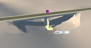
Bridge created in InfraWorks 360
Other Add-ons
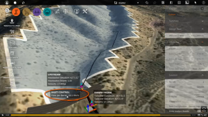
When InfraWorks 360 first came out for the 2015 version, there was some preview functionality (it timed out May 7th, 2014). Examples of this was Drainage Areas and Culvert Design. The Culvert Design tools did just that, it added a culvert under the roadway. The Drainage Areas would delineate the contributory area to a design point or road that crosses a drainage way. Remember, these are previews of upcoming technology and there is no guarantee that they will be a part of the final product (in other words, don’t buy the software expecting this functionality).
Licensing
This is the important part! If you have a suite version of InfraWorks, you’re good to go. Nothing new here. But, if you want InfraWorks 360, there are some things you have to be aware of.
Desktop Subscription
InfraWorks 360 and it’s add-ons are only available via Desktop Subscription. What is Desktop Subscription? It’s, in essence, a term license of the software. You purchase a license of InfraWorks 360 and you get access to it for a set term (1 month, quarter, or year). Another thing to note, this license is assigned to a specific user. That user needs an Autodesk ID (they are free) and that license will be assigned to that user. Your software manager can assign those licenses to what ever user in your organization you want.
The nice thing about Desktop Subscription is you can get the software for just the time you need. Got a project that you need 10 users to be able to access the software but the project is only going to last a year, you only pay for that software for a year.
More Information
If you want more information, check out the Autodesk website for comparing the different version of InfraWorks. Since the Autodesk website often changes, I’ve printed out that page and included a link to the .pdf HERE.
If you have any questions about this, make sure you talk to your reseller. If they can’t help you, let me know and one of the sales folks at CAD-1 can help you!