Yes, I know Civil 3D 2012 is coming out soon and yes, I’ll probably post about the tools that I think will be the most beneficial (I’ll let everyone else post the “Hey! Civil 3D 2012 is coming out!” posts) but sometimes things slip through the cracks and you find out there are cool new things available for what you already have.
Now, my question is; How did I miss this? Did this just come out? I did a search online and I can only find one reference to this outside of the Autodesk website so I’m assuming this is something really new (please correct me if I’m wrong). I probably missed it because of all of the focus on the announcements of the new AutoCAD Civil 3D 2012 that will be coming out soon.
One of the fine folks I follow on Twitter just posted a link to the Transportation Extension for AutoCAD Civil 3D 2011. I had never heard of such a thing so I went investigating and I found some really cool tools are available to everyone that has Civil 3D 2011. It’s not on the subscription site so I’m pretty sure it’s for everyone. Go to the home page for Civil 3D (http://www.autodesk.com/civil3d) and click on the Support link, and then the Utilities and Drivers link (a direct link to the page can be found HERE). Under AutoCAD Civil 3D 2011, you’ll see something called, “AutoCAD Civil 3D Transportation Extension”.
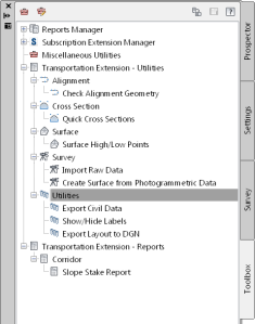
“What is this?” you may ask yourself, well, let me tell you what I’ve found out so far. It seems to be a bunch of additional tools that will run on top of Civil 3D 2011, and there looks to be some great tools in here. Allow me to list them for you and then later I will get into greater detail about them (at least the ones I’ve figured out so far):
1) Check Alignment Geometry
2) Quick Cross Section
3) Surface High/Low Points
4) Import Raw Data
5) Create Surface from Photogrammetric Data
6) Export Civil Data
7) Show/Hide Labels
8) Export Layout to DGN
9) Eleven New Reports (according to the readme)
That’s a lot of cool stuff they’ve given away for free (remember, this isn’t on the subscription website). So, let’s take a peek at what these tools will do.
1) Check Alignment Geometry
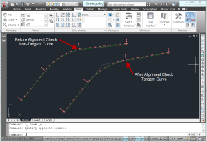
Have you ever created an alignment from existing entities and later found that those lines and curves that you received from the planner or surveyor or whoever weren’t tangent? Well, worry no more. This is a great little tool. In testing it, I created a polyline with a line segment, a tangent curve off the end of it, and then a line from the end of the curve that I drew so it looked tangent to the curve, but wasn’t actually tangent. I created an alignment from this polyline and then ran this tool on the newly created alignment. After running the command, it prompts you to select the alignment and then asks you to “Enter gap tolerance”. I’m not exactly sure what the gap tolerance is but probably has something to do with gaps in the alignment. There is no help so I can’t do any research on it and the little bit of testing I’ve done has helped me figure it out either. Next, it’s going to ask you to “Enter angle tolerance”. Again, I’m not exactly sure what the angle tolerance means but every time I’ve run it, I’ve used the default setting and it does something. So, what does it do to our example of a non-tangent line connected to an arc? Well, it makes them tangent. In addition to that, it place a PI at the point of intersection of the two lines (very convenient).
2) Quick Cross Section
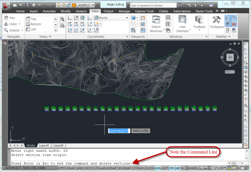
This is an interesting one and I’m not sure how useful it will be but, I’ll explain what I know about it. The Quick Cross Section command works very similarly to the Quick Profile command. I want to see what my cross sections will look like (real quickly) created from a line between here and there. Well, run the command and it will create them for you, all you need is a drawing with a surface in it. Once the command is run, it will prompt you for the surfaces you want to display in the sections and then it will prompt you for “Enter an option [3p/Multi]”. I haven’t tested the 3p option yet but Multi will allow you to pick points on the screen that will basically define the alignment you want to create the sections for. It will then prompt you for the sampling interval, the left and then the right swath width and where you want the sections to be displayed in the drawing. After you have entered that, a dialog box will be displayed that will ask you for the appropriate styles, Section Style, Section View Style, and Band Style Set (apparently there is no option for labels). Once you hit OK, the sections will be displayed in your drawing. Like a Quick Profile, the Quick Cross Sections are temporary. Unlike the Quick Profile, the Quick Cross Sections will immediately disappear when you end the command, rendering it (in my opinion) fairly useless.
3) Surface High/Low Points
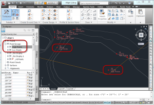
This command looks pretty cool. It will analyze a surface and place points at the high points and at the low points. You can then use the Low Point points as the starting point for the Catchment Area command. Basically, just run the command, and then select the area of the surface you want to be analyzed (if you want it to analyze the entire surface, just hit enter). It will also create two point groups, one for the high point points and one for the low point points (pretty convenient, huh?). You can then use these point groups to control the display (as well as the description) of the points.
4) Import Raw Data
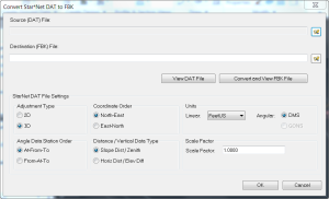
I wasn’t able to test this one out as I didn’t have any file types that would be needed for this command to work but, here is what I THINK it will do. It will take a Star*Net .dat file and convert it into a fieldbook file (for more information on Star*Net click HERE). From the import dialog box, there seem to be quite a few options.
5) Create Surface from Photogrammetric Data
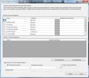
This one looks cool. I haven’t tested it out completely yet but, basically run the command and it will ask you what layer your data is on. Select the layers for both the linework and the point data (you have to give them names), select the surface you want to add them to (or have it create a new surface for you) and you’re done. I tested it with a bunch of contours and it didn’t give me the option to minimize flat faces (apparently they didn’t think that you could use this for contour data).
It appears there seems to be a slight issue with the dialog box. The bottom of it is cut off and no matter how you re-size the dialog, it doesn’t seem to fix it. If you are familiar with creating surfaces in Civil 3D, you shouldn’t have any trouble figuring out what is being cut off.
6) Export Civil Data
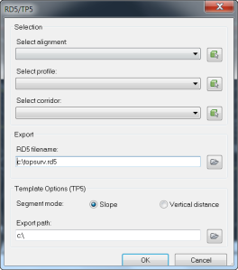
This is another one that I haven’t been able to test out as I don’t have any survey equipment. According to the readme file that comes with the extension, “Export Civil Data (to survey formats – RD5 and TP5) – enables users to export Civil 3D alignments, profiles, and corridors to a TDS .rd5 roadway file and/or .tp5 template file.” The dialog box asks you to select the Alignment, Profile, and (or?) the Corridor and it will create the .rd5 and the .tp5 files for you.
7) Show Hide Labels
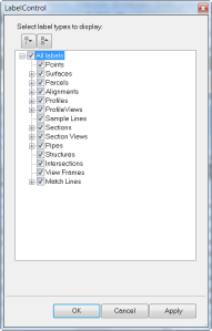
This is another one of those tools that looks pretty cool. Have you ever been looking at a drawing and though to yourself, “Man, I wish I could just get rid of those labels temporarily. It sure would make it easier to see what was going on!” Well, now you can. Simply run this command and the select the label types you want to hide and the ones you want to no longer be hidden. There’s even an option at the top to hide all labels or show all labels. Pretty slick in my opinion.
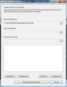
8) Export Layout to DGN
Pretty self explanatory here I would assume. It allows you to export a layout tab to a .dgn file. Again, I can’t truly test this one as I don’t have Microstation installed and I don’t have a “seed file”. It seems straight forward though. It will export each sheet (or just the ones you select) from a Sheet Set Manager file (.dst) to a .dgn file
9) New Reports
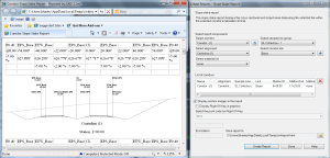
According to the read-me, there are 11 new reports. Well, I have no reason to doubt that but, when you install it, there is a new report category and it only shows one new report so the other new reports must be included in the other report categories somewhere (I don’t have a list of them or of the originals that come with C3D to compare my current list to). The one that does show up (Corridor->Slope Stake Report) is pretty slick as it will actually display the cross sections in the report for a visual confirmation of the data.
Wrap Up
As I said, there are some pretty cool new tools here so go out and try it for yourself. Let me know what you think, what reports you like that are new with this, etc. Also note that when you download it, you can also download the CalTrans Content Kit after you install these tools. Looks like I may have another post to write up about that.
March 29, 2011 at 12:37 pm
Thanks for leeting us know this is available!!! And thanks for the write-up, very informative, especially considering there was no help to pull info from. Now to download and see what we can use….
March 30, 2011 at 5:45 am
Hi Mark,
I’m glad it piqued your interest. Let me know what tools you find helpful!
May 9, 2011 at 1:51 pm
we were not success first try to convert alignments to a readable road file
we kept getting the following error:
Point named ‘cgsa_c3d_gethelem2_dotNET’ in DLL’AeccDOT02.arx’
has anyone encountered this?
September 2, 2011 at 10:06 am
Dale H.
where does a person find the readme file and after you run the exe what do you appload. I have never used an extension before.
September 2, 2011 at 10:37 am
The readme file is on the website where you can download the extension. Once the extension is installed, you don’t have to load anything, it is installed into your toolbox on your toolspace. If you don’t see the toolbox, go to your Home tab on the ribbon and toggle it on (there are four buttons to the right of the big Toolspace button and one of those will turn it on).